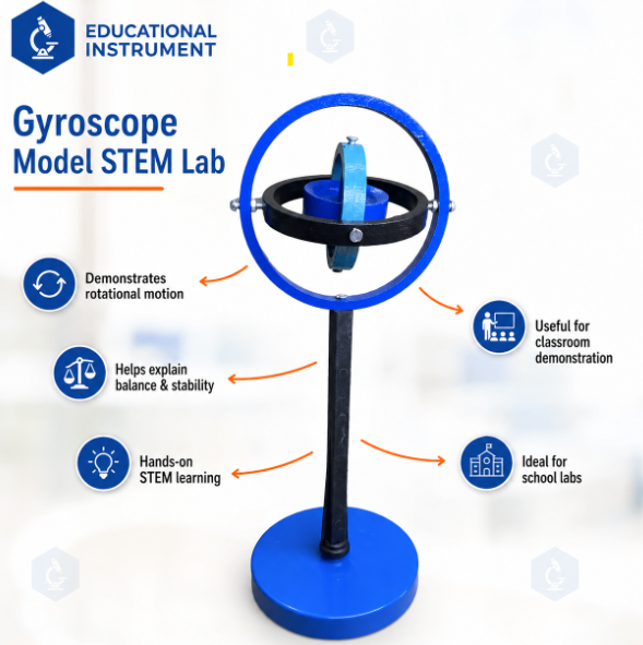
Gyroscope Model STEM Lab
Product Code : SCL-MH-12558
Introduce students to the complex and fascinating physics of rotational kinematics, torque vectors, and angular velocity transitions with the professional-grade Gyroscope Model STEM Lab Kit, precision-engineered by Educational Instrument India. Designed to satisfy the rigorous pedagogical criteria of secondary school physics practicals, university physics workshops, and institutional engineering laboratories, this premium apparatus turns challenging vector cross-product math into intuitive physical discoveries.
Unlike cheap toy plastic stabilizers that lose momentum rapidly or wobble due to poor machining, this laboratory-grade model features a solid, dynamically balanced high-inertia brass flywheel rotor. The flywheel is mounted inside a low-friction 3-axis gimbal ring matrix made from anodized structural alloy. This open design gives the assembly three complete rotational degrees of freedom, allowing the core axis to orient itself arbitrarily in space. When the flywheel is spun up to high velocity via the included pull-cord or localized electronic starter motor, it builds a massive angular momentum vector. If a non-planar external force or hanging balance weight attempts to tip the spin axis, the gyroscope reacts counter-intuitively by rotating perpendicular to the applied force vector, directly illustrating torque-induced precession.
Perfect for high school AP physics blocks, aeronautical science classrooms, maritime navigation training centers, and advanced STEM academies, this kit helps students master complex mechanics. The heavy, non-slip pillar stand and adjustable balancing slider arm allow users to accurately change variables, isolate center-of-mass offsets, calculate moment of inertia constants, and record uniform precession velocities under varying structural loads.
Core Pedagogical and Technical Key Features:
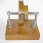
Dynamically Balanced Flywheel: Precision-machined solid brass wheel minimizes vibrations and extends spin times, ensuring stable data tracking during class experiments.
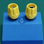
Low-Friction Pivot Bearings: Adjustable hardened steel cone-pivot bearings inside the gimbals isolate the wheel from external friction losses and parasitic dampening forces.
Multi-Axis Gimbal Flexibility: Concurrently tracks pitch, roll, and yaw vectors, enabling clear demonstrations of inertial navigation rules used in aerospace engineering.
Adjustable Counterweight Slider: Features an integrated sliding weight lock on the extension axis to vary applied gravitational torque with millimeter precision.
STEM Curriculum Mapping: Optimized for verifying the conservation of angular momentum, tracing torque direction cross-products , measuring precession frequencies, and tracking nutation anomalies.
- Product Specifications
|
Parameter Matrix |
Technical Engineering Specification Details |
|
Brand Name |
Educational Instrument India |
|
Product Classification |
Rotational Mechanics & Rigid Body Dynamics / STEM Lab Equipment |
|
Flywheel Rotor Metallurgy |
Dynamically balanced, solid high-purity brass with a polished protective coating |
|
Gimbal Ring Configuration |
3-Axis nested frame rings engineered from anodized, high-strength structural aluminum alloy |
|
Bearing Assembly Type |
Micro-adjustable hardened steel cone-and-cup pivot point assemblies |
|
Excitation/Spin Interface |
Dual System: High-tensile braided nylon pull-cord grip or attachable friction drive motor adapter |
|
Support Base Assembly |
Heavy-duty cast iron stable pedestal pillar with a gimbal receiver socket cup |
|
Flywheel Dimensions |
Diameter 75 mm; Thickness: 15 mm |
|
Total Assembled Profile |
Approx |
|
Net Apparatus Weight |
Approx. 1.45 kg (Heavy mass centers the base to prevent skidding during high precession torque) |
- How to Use the Gyroscope Model STEM Lab Kit
Ensure successful educational experiments and capture clean rotational metrics by executing your laboratory protocols using this standard technical methodology:
EXPERT EXPERIMENTAL CONFIGURATION NOTICE: To accurately demonstrate pure gyroscopic precession, align the counterweight slider arm so the nested gimbal frame is perfectly balanced and horizontal before spinning the rotor. This establishes a true zero-torque equilibrium baseline.
Base Installation and Bearing Tuning: Position the heavy cast iron pillar stand on a level, solid laboratory bench. Inspect the gimbal ring pivot points. Ensure they are snug yet free-moving; loose screws disrupt alignment, while over-tightened pins introduce friction binding.
Rotor Spin-Up and Excitation:
Thread the high-tensile nylon cord into the core spindle aperture hole on the brass flywheel shaft axis.
Wind the string firmly around the axle by rotating the wheel manually.
Grip the outer gimbal ring frame securely with one hand, and pull the nylon cord straight outward with a fast, continuous stroke to spin the flywheel to peak operational RPM.
Demonstrating Vector Rigidity in Space:
Hold the outer frame stand and walk across the laboratory, or rotate the support stand body in a circle.
Have students note that the spinning flywheel rotor axis maintains its absolute heading direction in space, completely ignoring your movements. This demonstrates the physics principle of gyroscopic stability or directional rigidity.
Executing Torqued Precession Calculations:
Rest the base of the spinning gyroscope spindle hub directly into the receiver cup on top of the vertical pedestal stand.
Slide the adjustable counterweight arm outward away from the center to create a center-of-mass offset.
Instead of falling down due to gravity, the gyroscope will begin a steady horizontal orbit around the vertical pillar axis.
Instruct the class to track this behavior and map the torque-induced precession formula using their data points
Where represents the applied gravitational torque vector, is the visible horizontal precession frequency, and is the active angular momentum of the flywheel.
- Frequently Asked Questions (FAQs)
Q1: Why doesn't the spinning gyroscope tip over due to gravity when placed on the pedestal stand?
A: This behavior is a direct result of Newton’s Laws applied to rotating systems. When the flywheel is spinning, it possesses a massive angular momentum vector pointed along its spin axis. When gravity pulls downward on the off-center wheel, it creates an external torque vector that is perpendicular to the spin axis. According to rotational physics equations, torque dictates the rate of change of angular momentum. Instead of moving downward, the original angular momentum vector shifts sideways toward the direction of the applied torque, causing the entire assembly to precess horizontally rather than fall over.
Q2: What is the mechanical benefit of a solid brass flywheel over steel or polymer wheels?
A: The magnitude of a gyroscope's stability depends entirely on its total moment of inertia . Brass has a high material density and mass profile. By concentrating this heavy mass along the outer rim of the flywheel rotor, the gyroscope maximizes its rotational inertia at any given speed. This gives it a significantly larger angular momentum baseline, which yields longer spin times and clearly visible precession dynamics that resist friction dampening.
Q3: Why does the gyroscope occasionally bob up and down while precessing in a circle?
A: This secondary nodding or bobbing motion is a distinct physical phenomenon known as nutation. Nutation occurs when the gyroscope is released with a slight downward push or when the initial precession speed does not exactly match the system's gravitational torque requirements. The gyroscope naturally corrects for this energy imbalance by tracing a small wave path while it settles into its stable horizontal precession loop.
Q4: How should the precision cone bearings be cleaned and maintained between semesters?
A: To keep friction values minimal, the steel pivot pins and brass cup points must remain free of dust, grease, and moisture. Clean the bearing points periodically by wiping them with a lint-free microfiber cloth dipped in a small drop of isopropyl alcohol. Apply a single drop of fine, ultra-low viscosity instrument oil to the pivot contacts once a year before storage to protect the metal faces from oxidation and rust.